High voltage
Electrical insulation resistance test: test voltage, procedure, PI and DAR
An electrical insulation resistance test, often called a "megger test" after the trade name of early insulation testers, is the quickest health check for motors, generators, cables, transformers and switchgear. A DC test voltage is applied across the insulation, the current that flows is measured, and the instrument shows the result in megohms or gigohms. Read on its own, one number says little. Read over time, and with the polarization index, it shows whether insulation is clean and dry or damp, dirty and ageing. This guide explains how to choose the test voltage, how to run the test and how to read IR, PI and DAR.
What the instrument actually measures
When a DC voltage is applied to insulation, three currents flow:
- Capacitive charging current, which is large at first and dies away within seconds.
- Absorption (polarization) current, which falls slowly over minutes as the insulation material polarizes.
- Leakage current, which stays constant: through the insulation and across its surface.
Because the first two decay, the resistance reading rises with time. In good, dry insulation it keeps rising for many minutes; in damp or contaminated insulation, leakage dominates and the reading levels off quickly. That difference is what the polarization index captures.
Choosing the test voltage
Use the test voltage given in your procedure or the equipment standard. For rotating machines, IEEE 43 recommends the following:
| Winding rated voltage | Insulation resistance test voltage (DC) |
|---|---|
| below 1000 V | 500 V |
| 1000 – 2500 V | 500 – 1000 V |
| 2501 – 5000 V | 1000 – 2500 V |
| 5001 – 12,000 V | 2500 – 5000 V |
| above 12,000 V | 5000 – 10,000 V |
Medium-voltage cables, transformers and switchgear are commonly tested at 2.5 kV, 5 kV or 10 kV. A higher test voltage stresses the insulation closer to service conditions and reveals weak points that a low voltage misses.
Running the test
- Isolate, earth and discharge the equipment. Disconnect anything that must not see the test voltage, such as electronics, surge arresters and voltage transformers.
- Clean and dry the terminations and bushings, and record the winding or ambient temperature and the humidity.
- Connect: L (line) to the conductor under test, E (earth) to the frame, screen or the other conductors tied together, and G (guard) where surface leakage would distort the reading, for example to a bare conductor ring on a bushing or cable termination.
- Apply the test voltage and read the resistance at 30 seconds, 1 minute and, for a polarization index, 10 minutes.
- Discharge: switch off and let the instrument discharge the object, then earth it. A large capacitive object such as a long cable or a big winding stores charge; leave it earthed for at least four times the test duration before handling.
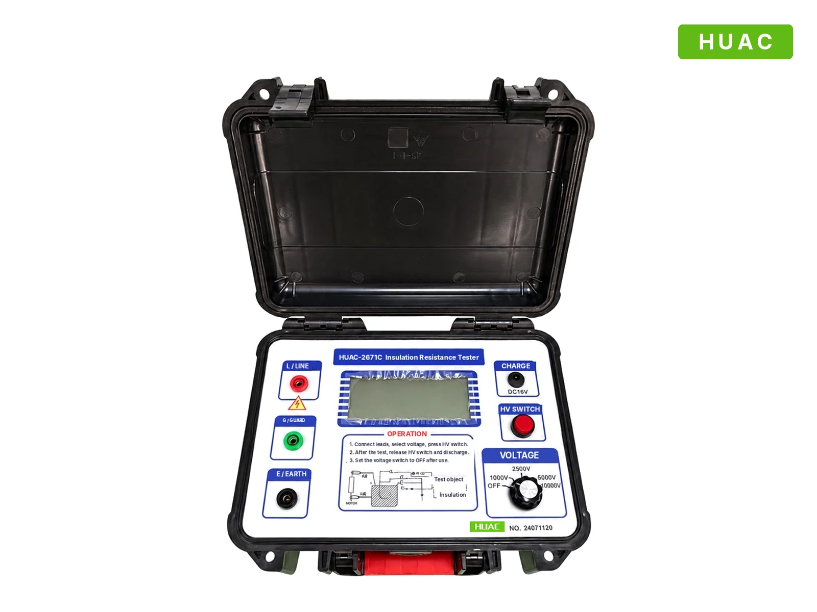
Reading the results
Insulation resistance (IR)
Absolute values depend strongly on the size, type and temperature of the equipment, so the trend is the most useful guide. Compare with the factory value, earlier tests and identical equipment. For rotating machines, IEEE 43 gives recommended minimum values for the 1-minute reading corrected to 40 °C, for example 100 MΩ for most form-wound stator windings built after 1970 and 5 MΩ for random-wound windings below 1 kV.
Polarization index (PI)
PI = R10 min / R1 min
Because both readings are taken at the same temperature, the PI largely cancels the effect of temperature and the size of the object. IEEE 43 recommends a minimum PI of 2.0 for class B, F and H insulation. A PI close to 1 means the reading did not rise: leakage dominates, usually because of moisture or contamination. Note that when the 1-minute reading is already very high, above about 5 GΩ, the PI may not be meaningful.
Dielectric absorption ratio (DAR)
DAR = R60 s / R30 s
A shorter version of the same idea, useful when a 10-minute test is not practical. Values around 1.0 indicate poor insulation; values well above 1.25 are generally a good sign. Use your own procedure's limits where they exist.
Temperature and humidity
Insulation resistance falls sharply as temperature rises, roughly halving for every 10 °C for many insulation systems. Always record the temperature and, when comparing with earlier results, correct to a reference temperature using the factors in your standard. Test above the dew point: condensation on the surface makes the reading low for reasons that have nothing to do with the insulation itself. The guard terminal helps separate surface leakage from leakage through the insulation.
Common mistakes
- Testing with the object still connected to other equipment, so the reading includes everything in parallel.
- Reading too early on a capacitive object, before the charging current has died away.
- Not using the guard on dirty or damp bushings and terminations.
- Touching the leads or the object before it is fully discharged.
Equipment
The HUAC-2671C insulation resistance tester offers 1, 2.5, 5 and 10 kV, a range up to 199.9 GΩ and a guard terminal, in a rugged case of about 1 kg. For a full insulation assessment, combine it with a tan delta test and, for cables and large apparatus, an AC withstand test such as a series resonant test.