High voltage
Series resonant AC withstand test: step-by-step procedure for cables and GIS
A series resonant AC withstand test is the standard way to prove the insulation of a new high-voltage cable, a GIS or a large transformer on site. The equipment is simpler than it looks, and most failed tests are caused by preparation and tuning problems, not by the insulation. This guide walks through a complete test on a cable circuit, from preparation to the test record, and explains what to do when the system will not tune or the test trips.
Why a resonant test instead of a test transformer
A cable or GIS is a large capacitor. At test voltage it draws a charging current of several amperes, and a conventional test transformer would have to supply all of that reactive power. In a series resonant circuit, a reactor in series with the test object is tuned so that its inductance cancels the capacitance. The source then only supplies the losses, which are smaller than the reactive power by the quality factor Q of the circuit, typically 30 or more. That is why a resonant system that fits on a small truck can test a long 110 kV cable. The theory and sizing are covered on our high voltage test equipment page; this article is about running the test.
Which voltage and duration?
Take the test voltage, frequency range and duration from the cable standard and the project specification, never from memory on site. For extruded cables, IEC 60502-2 (up to 30 kV), IEC 60840 (above 30 kV up to 150 kV) and IEC 62067 (above 150 kV) all allow after-installation AC tests at frequencies between 20 and 300 Hz. IEC 60840 and IEC 62067 specify a one-hour test at the voltage given in the standard, or a 24-hour test at normal operating voltage as an alternative. Write the agreed voltage, duration and frequency range on the test plan before you go to site.
Step 1: Prepare the test object
- Isolate and earth the circuit on both ends according to your switching procedure, and confirm isolation before anyone touches the conductors.
- Disconnect what must not be tested: surge arresters, voltage transformers and any equipment not rated for the test voltage. Leave enough clearance from the open terminals.
- Clean and dry the terminations. Surface leakage and corona at a dirty or wet termination are a common cause of a low Q and of unstable voltage.
- Earth the phases not under test and the metallic screens or sheaths, unless the procedure says otherwise.
- Fence off the far end of the cable and put a person with a radio there. The far end is at full test voltage.
Step 2: Set up and connect the system
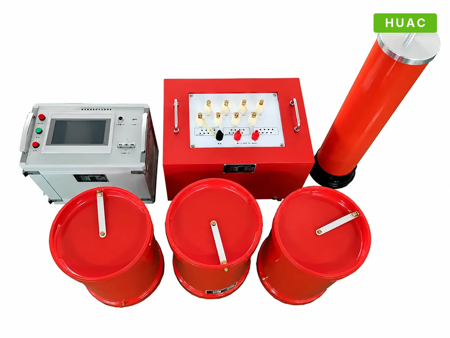
A variable frequency series resonant system has four main parts, connected in this order:
- Variable frequency power source and control unit, supplied from the site supply.
- Excitation transformer, which steps the source output up to the reactor input voltage.
- High-voltage reactors, connected in series for more voltage or in parallel for more current, as calculated for this test object.
- Capacitive voltage divider, connected in parallel with the test object to measure the actual test voltage.
Run the high-voltage lead from the top of the reactor stack to the cable termination by the shortest path, with smooth corona-free fittings and no sharp ends. Make one solid earth connection for the whole system at a single point, with heavy earth leads from the control unit, excitation transformer, reactors and divider to that point. Poor earthing is the most common cause of measurement noise and of nuisance trips.
Step 3: Tune at low voltage
Enter the test voltage, the duration and the voltage divider ratio in the control unit, then start the automatic frequency sweep. The system applies a low excitation and sweeps from 30 to 300 Hz, watching the voltage at the divider. At resonance the voltage peaks sharply; the control unit locks onto that frequency.
Check three things before you raise the voltage:
- The resonant frequency is inside the range allowed by the standard and by your specification.
- The quality factor is in the normal range for the setup. An unusually low Q points to leakage, corona or a poor connection.
- The calculated current at full test voltage is within the reactor rating.
Step 4: Raise the voltage and hold
Raise the voltage smoothly to the test level, watching the voltage, current and frequency readings. Once at the test voltage, start the timer and hold. The control unit keeps the system at resonance as the capacitance changes slightly with temperature. Record the voltage, frequency and current at the start, at intervals during the test and at the end.
Step 5: Finish, discharge and earth
At the end of the test period, reduce the voltage to zero and switch off the output. A cable holds a dangerous charge after the test. Discharge it through the discharge rod, first through the resistor and then directly, and apply the working earths before anyone disconnects the high-voltage lead. Then move to the next phase and repeat from Step 3.
Reading the result
The withstand test is a pass or fail test: the insulation passes if it withstands the test voltage for the full duration without breakdown. If the insulation breaks down, the resonance collapses instantly because the fault short-circuits the capacitance. The voltage drops to almost zero and the flashover protection switches off the output. The fault position can then be located with a cable fault locator, for example a high voltage bridge fault locator for high-resistance faults.
If your specification also calls for partial discharge measurement during the test, the resonant system provides a low-distortion sine wave suitable as the voltage source for a separate PD measuring system.
Troubleshooting
| Symptom | Likely cause | What to do |
|---|---|---|
| Resonant frequency above 300 Hz | Test object capacitance too small for the reactor configuration | Connect reactors in series for more inductance, or add capacitance with the divider or a compensation capacitor |
| Resonant frequency below the allowed minimum | Capacitance too large, for example a long cable | Connect reactors in parallel; if that is not enough, the system needs more reactor capacity for this length |
| Low Q, voltage will not rise | Corona, surface leakage, poor HV connections, damp terminations | Clean and dry terminations, check fittings and clearances, check the earth connections |
| Trips during the voltage rise with no breakdown | Overcurrent setting too low, unstable supply, flashover at the HV lead | Check the protection settings, the site supply and the HV lead route |
| Unstable voltage reading | Divider ratio entered wrongly, poor earth, interference | Check the divider settings and use a single-point earth |
What goes in the test record
- Test object: circuit name, cable type, cross-section, length, phase
- Standard and specification, test voltage, frequency, duration
- Reactor configuration, measured capacitance or current, quality factor
- Voltage, frequency and current readings during the test
- Result: withstood, or breakdown with time and voltage
- Ambient temperature and humidity, date, names of the test team
Choosing a system
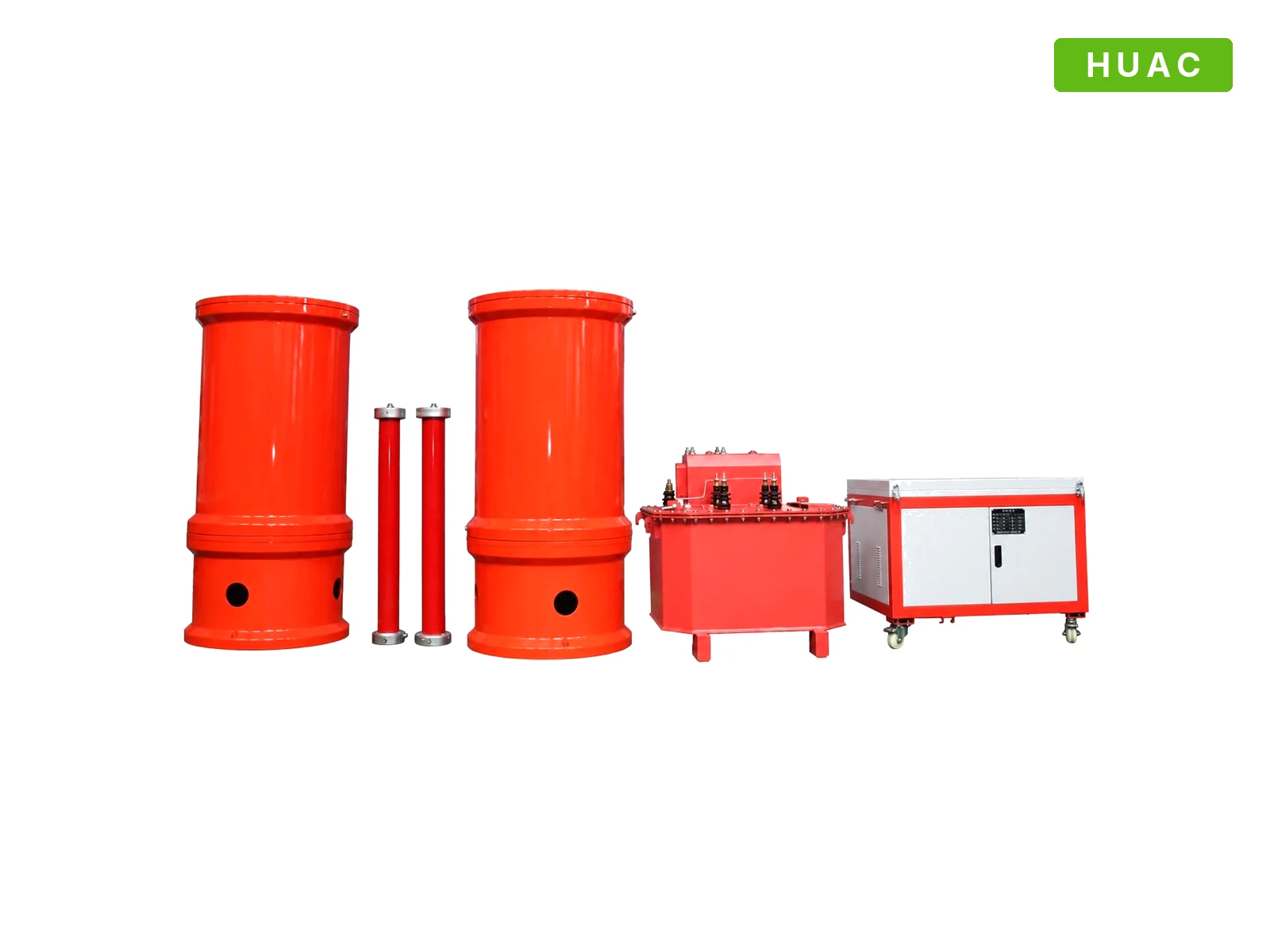
A resonant system is sized for the largest capacitance and the highest test voltage you need to cover. HUAC builds systems from 10 kV and 35 kV distribution classes up to 110 kV / 220 kV and 500 kV. For a comparison with very low frequency testing of medium-voltage cables, see VLF vs. series resonant testing. Send us the cable data and test voltage, and our engineers will confirm the configuration.