Transformer
Transformer winding resistance testing: procedure, temperature correction and results
Winding resistance is one of the simplest transformer tests and one of the most useful. A single DC measurement per winding and tap position reveals loose connections, broken strands, burnt tap changer contacts and wrong internal connections, often long before they show up as hot spots or dissolved gas. The catch is that the measurement looks easy and is easy to get wrong. This guide covers how to set the test up, how to correct for temperature and how to read the results.
What the test finds
The DC resistance of a winding depends only on the conductor and every joint in the current path. Anything that adds resistance shows up in the reading:
- Poor connections at bushings, lead joints and winding terminations.
- Broken or damaged strands in multi-strand or continuously transposed conductors.
- Tap changer problems: worn, pitted or coked contacts in on-load and off-circuit tap changers, and selector contacts that do not make properly.
- Shorted turns, which lower the resistance of the affected phase. Shorted turns are usually easier to see on a turns ratio or excitation current test, so use those tests to confirm.
- Wrong internal connections after manufacture or repair.
Winding resistance is a routine factory test under IEC 60076-1, and IEEE C57.152 describes it as a standard diagnostic field test. The factory values on the test report are the reference you will compare against for the life of the transformer.
Before you start: safety and preparation
Isolate and earth the transformer and disconnect it from the system on all sides. Record the top-oil temperature, and if the transformer has just been taken out of service, wait until the winding temperature has settled close to the oil temperature, otherwise you will not know what temperature you measured at.
A winding is a large inductance. When the test current is switched off, the stored energy has to go somewhere, and an open lead can produce a dangerous voltage across it. Never disconnect a test lead while current is flowing, and let the instrument discharge the winding completely before you touch the connections. A good winding resistance tester discharges automatically and shows when it is safe to change leads.
How to connect
Always use a four-wire (Kelvin) connection: two leads carry the current and two separate leads measure the voltage. The voltage leads should be connected directly at the bushing terminals, inside the current clamps, so that the resistance of the clamps and leads is not included in the result.
- Star (wye) windings with an accessible neutral: measure each phase from line terminal to neutral.
- Delta windings, or star windings without a neutral: measure between line terminals. Each reading then includes more than one phase, so compare the three line-to-line readings with each other and with the factory report, which is usually given in the same way.
- Tapped windings: measure on every tap position, not just the principal tap, so that every tap changer contact is checked.
Getting a stable reading
When DC is applied, the current rises slowly because of the winding inductance. The reading is only valid once the current, and therefore the voltage drop, is steady. On large transformers this can take minutes. The time depends on the ratio of inductance to resistance, which is why a higher test current helps: once the core is saturated, the effective inductance drops and the reading settles much faster.
Choose a test current high enough to saturate the core but no more than about 10 % of the winding's rated current, so that the measurement does not heat the winding. Wait until the instrument shows a stable value before you record it. Testers with an automatic stability check, such as the HUAC-3540, take the guesswork out of this step.
Two practical tips save a lot of time on large units. First, test the high-voltage and low-voltage windings of the same phase together where your instrument allows it, which saturates the core faster. Second, change tap positions with the current flowing only if the instrument and the tap changer are designed for it; otherwise switch the current off, discharge, change tap and start again.
Temperature correction
Copper and aluminium resistance rises with temperature, so readings taken at different temperatures cannot be compared directly. Correct every reading to a common reference temperature, normally the one used in the factory report:
Rref = Rmeas × (Tk + Tref) / (Tk + Tmeas)
- Tk = 235 for copper (IEEE uses 234.5) and 225 for aluminium.
- Tmeas is the winding temperature at the time of the test, usually taken as the average oil temperature on a de-energised, settled unit.
- Tref is the reference temperature, for example 75 °C as used in IEC 60076-1 for loss and impedance values.
Example: a copper winding reads 0.4120 Ω at 22 °C. Corrected to 75 °C: 0.4120 × (235 + 75) / (235 + 22) = 0.4120 × 310 / 257 ≈ 0.4970 Ω.
How to read the results
| Comparison | What to look for | Likely cause if it fails |
|---|---|---|
| Phase to phase, same tap | The three phases should agree closely. Many utilities use about 2 % as an alert level. | Poor joint or damaged conductor in the higher phase |
| Against the factory report | Temperature-corrected values close to the original | Deterioration since manufacture, or wrong connection |
| Tap to tap | Even steps from one tap position to the next | A step that is out of line points to a worn or dirty tap contact |
| Against the last test | No upward trend | Progressive contact wear or a loosening joint |
The alert levels used by utilities differ, so always use the criteria in your own maintenance standard or the manufacturer's instructions. A single reading that is slightly high is a reason to retest, not to open the transformer: check the clamps, clean the bushing terminals and measure again before drawing a conclusion.
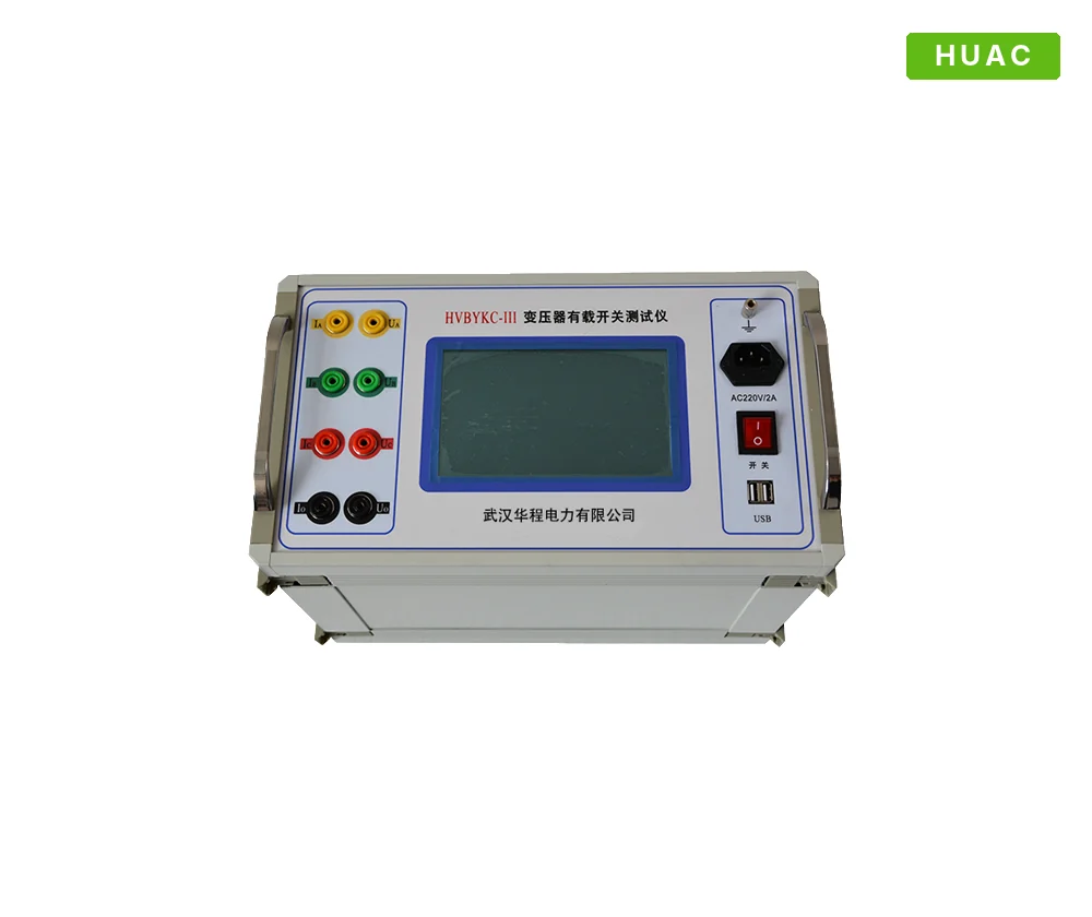
If the readings change with the tap position in an irregular way, follow up with a dynamic OLTC test, which records the transition resistance and timing while the tap changer is operating.
Demagnetise after the test
The DC test current leaves residual magnetism in the core. This does not harm the transformer, but it can cause a high inrush current at energisation and it distorts other diagnostic tests, especially sweep frequency response analysis and excitation current measurements. Demagnetise the core after the winding resistance test, either with the demagnetising function of the tester or with the method recommended by the transformer manufacturer.
Frequently asked questions
What test current should I use for winding resistance?
Use enough current to saturate the core so the reading stabilises quickly, but no more than about 10 % of the winding's rated current to avoid heating it. Small distribution transformers may need only a few amperes; large power transformers often need 10 to 40 A.
Why does the reading keep drifting?
The core is not yet saturated, so the current is still rising. Wait longer, increase the test current, or inject into the high- and low-voltage windings together. A drifting reading can also come from a poor clamp connection.
Do I need to correct winding resistance for temperature?
Yes. Resistance changes by roughly 0.4 % per °C for copper, so a reading taken 20 °C apart from the factory test can differ by around 8 % even on a healthy transformer. Correct all readings to the same reference temperature before you compare them.
Should I measure every tap position?
Yes. Measuring only the principal tap misses the contacts that are not in use on that position, and worn tap changer contacts are one of the most common faults this test finds.