Transformer
Transformer turns ratio (TTR) test: how it works and how to read the results
A transformer turns ratio (TTR) test checks that the ratio between the windings is what the nameplate says, on every tap position, with the right polarity and vector group. It is a quick, low-voltage test, yet it is the most direct way to find shorted turns, open windings and tap changer faults. This article explains how the test works, what the tolerances are and how to read results that look wrong.
How a turns ratio test works
The tester applies a low AC voltage to one winding, usually the high-voltage side, and measures the voltage induced on the corresponding low-voltage winding. The ratio of the two voltages equals the turns ratio, because at no load the voltage drop in the windings is negligible. Modern three-phase testers apply the voltage to each phase in turn, compare the phases with the declared vector group and report ratio error, phase angle and excitation current for every phase.
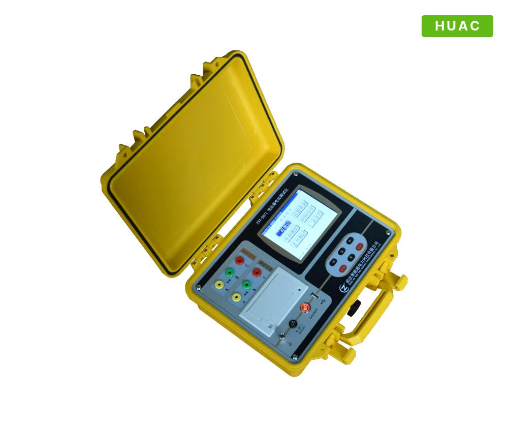
Because the test voltage is low, typically tens to a few hundred volts, the test is safe for the transformer and quick to run. A battery-powered tester such as the HUAC-2071 measures ratio, vector group and polarity of a three-phase transformer with a single connection.
When to run it
- Acceptance and commissioning, to confirm the nameplate data and catch transport damage or wrong internal connections.
- After a fault or protection trip, when you need to know whether the windings are damaged before re-energising.
- After tap changer maintenance or repair, to confirm every position is connected correctly.
- Routine diagnostics, together with winding resistance and insulation tests, to build a trend over the life of the transformer.
Connecting the tester
Isolate and earth the transformer and disconnect all external connections, including the neutral earth if your procedure allows it. Connect the high-voltage leads to H1, H2, H3 (and H0 if present) and the low-voltage leads to X1, X2, X3 (and X0), following the marking on the tester. A swapped lead is the most common cause of a "failed" test, so check the connections before you suspect the transformer.
Enter the nameplate voltages and vector group, or use the automatic vector group detection if the tester has it. Then measure on every tap position of the tap changer.
Acceptance limits
Both IEC and IEEE limit the ratio deviation to about half a percent:
- IEC 60076-1: on the principal tapping, the measured ratio must be within ±0.5 % of the declared ratio, or within ±1/10 of the actual percentage impedance, whichever is smaller. Other tappings follow the agreement in the specification.
- IEEE C57.12.00: the turns ratio must be within 0.5 % of the nameplate voltage ratio.
The ratio error is calculated as (measured ratio − nameplate ratio) / nameplate ratio × 100 %. A good tester calculates it for you on each tap.
Reading the results
| Symptom | Likely cause | Next step |
|---|---|---|
| Ratio error above 0.5 % on one phase, high excitation current on that phase | Shorted turns | Confirm with winding resistance and dissolved gas analysis before re-energising |
| No reading, or a very large error, on one phase | Open winding or broken lead | Check continuity and winding resistance |
| Error only on certain tap positions | Tap changer selector or contact fault, or wrong tap lead | Inspect the tap changer; run a dynamic OLTC test |
| Errors on all phases with the same pattern | Wrong nameplate data or vector group entered, or swapped leads | Check the settings and connections, then repeat |
| Phase angle deviation | Wrong vector group or internal connection error | Check the vector group against the nameplate |
Why excitation current matters
Most three-phase testers also record the excitation current drawn on each phase during the test. On a healthy core-type transformer, the two outer phases draw similar currents and the centre phase draws less, because its magnetic path is shorter. A shorted turn acts like a loaded secondary and raises the excitation current on its phase, sometimes before the ratio error is large enough to fail. Compare the excitation currents with each other and with earlier tests at the same voltage.
Common mistakes
- Residual magnetism from a previous DC test, such as winding resistance, can distort excitation current readings. Demagnetise the core first, or run the ratio test before the DC tests.
- Testing only the principal tap. Tap changer faults show up only on the affected positions.
- Ignoring the test voltage. Excitation current depends on the test voltage, so trend it only against tests at the same voltage.
- Testing with external connections still attached. Connected cables, surge arresters or other equipment can load the windings and distort the results.
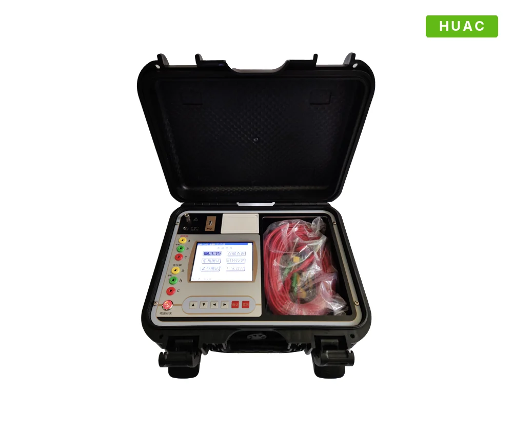
For larger test programmes, a fully automatic turns ratio tester with blind testing identifies the vector group without prior information, and a tester with a built-in printer gives a record on site.
Frequently asked questions
What is an acceptable turns ratio error?
Within ±0.5 % of the nameplate ratio. IEC 60076-1 also allows the limit to be tighter, at one tenth of the percentage impedance, if that is smaller. Check your purchase specification for the limits on tap positions other than the principal tap.
Can a turns ratio test find shorted turns?
Yes. Shorted turns change the effective ratio of the affected phase and raise its excitation current. Even a small change on one phase, compared with the other two, is worth investigating.
Should the turns ratio test be done before or after winding resistance?
Ideally before. The DC current used for winding resistance leaves residual magnetism in the core, which affects excitation current readings. If you must test afterwards, demagnetise the core first.
Does the test voltage affect the ratio?
The ratio itself should not change with test voltage on a healthy transformer, but the excitation current does. Record the test voltage with every result so that later tests can be compared.